other
  • The Advantages of Solar Street Lights
    The Advantages of Solar Street Lights
    Sep, 07 2026
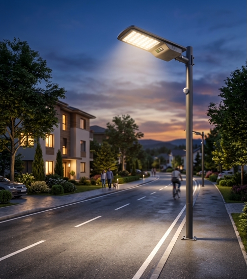
    As global urbanization accelerates and the urgent need for sustainable infrastructure grows, solar-powered street lights have emerged as a revolutionary solution for illuminating public spaces worldwide. By harnessing the abundant and renewable energy of the sun, these modern lighting systems go far beyond simple illumination. They provide a wide array of financial, environmental, and practical benefits, making them a cornerstone of modern "smart city" development and rural empowerment.   Here is an in-depth look at the advantages of integrating solar street lighting into your next project: 1. Unmatched Cost-Efficiency and High ROI The most immediate benefit of solar street lights is the drastic reduction in operational costs. Because they run entirely on captured sunlight, they completely eliminate monthly electricity bills. This shields municipalities and businesses from unpredictable fluctuations in the energy market. Furthermore, the long-term Return on Investment (ROI) is exceptional, allowing organizations to reallocate funds that would normally be spent on utility bills toward other vital community projects.   2. Profound Eco-Friendly Impact Utilizing renewable energy is one of the most effective ways to drastically reduce a community’s carbon footprint. Traditional grid-tied street lights rely heavily on fossil fuels, contributing significantly to global warming. By switching to solar alternatives, you actively lower air pollution and CO2 emissions. This sustainable approach helps cities meet their net-zero climate goals and protects local ecosystems for future generations.   3. Complete Grid Independence and Resilience Equipped with high-efficiency solar panels and deep-cycle batteries, these lights generate, store, and manage their own power independently. A standard 6 to 8-hour charge under direct sunlight can provide up to 12 to 15 hours of reliable nighttime illumination. Because they operate off-grid, solar lights are immune to local power outages, rolling blackouts, and infrastructure failures, ensuring that streets remain safely lit even during extreme weather events or grid emergencies. 4. The Perfect Solution for Remote and Challenging Locations The self-sustaining nature of solar lighting makes it the ultimate choice for areas where extending the electrical grid is physically impossible or prohibitively expensive. They are widely deployed in rural villages, isolated highways, remote construction sites, and disaster recovery zones. They bring safety and visibility to off-grid communities without the need for massive infrastructure investments.   5. Hassle-Free Installation and Minimal Disruption Installing traditional street lights requires extensive trenching, underground wiring, and repaving, which disrupts traffic and drives up labor costs. Modern solar lights—especially "all-in-one" designs that seamlessly integrate the LED fixture, solar panel, and battery into a single sleek unit—eliminate this complex groundwork. They offer a simple "plug-and-play" installation process that requires minimal manpower and can be completed in a fraction of the time.   6. Automated Smart Operation and IoT Integration Today's solar street lights are equipped with intelligent charge controllers and environmental sensors. They automatically detect ambient light levels, turning on at dusk and off at dawn without any human intervention. Many advanced models also feature motion sensors (PIR) that keep the light at a dim, energy-saving level when the area is empty, instantly brightening to 100% capacity when a pedestrian or vehicle approaches.   7. Enhanced Public Safety and Security Bright, consistent lighting is a proven deterrent to crime and significantly reduces nighttime traffic accidents by improving driver visibility. Additionally, solar street lights operate on low-voltage Direct Current (DC), completely eliminating the risk of fatal electrocution associated with high-voltage Alternating Current (AC) wiring. Some commercial units even feature integrated, solar-powered security cameras to monitor public spaces continuously.   8. Exceptional Durability and Low Maintenance Because high-quality LED components and modern lithium batteries operate under less thermal stress than traditional high-pressure sodium lamps, solar lights boast an impressively long lifespan. Built with weather-resistant materials (often IP65-rated or higher), they can withstand harsh elements such as heavy rain, snow, and extreme heat for up to 10 years. Integrated smart sensors can also alert maintenance teams to specific component faults, making routine check-ups fast and incredibly cheap.   A Brighter, Greener Future Awaits Solar street lighting is the ultimate, forward-thinking solution for eco-conscious, affordable outdoor illumination. A single high-powered solar street light can easily and effectively illuminate an area of over 2,700 square feet.   To put the environmental impact into perspective: a single traditional street lamp produces approximately 144 kg of CO2 annually. By transitioning thousands of lights to solar power, we can eliminate massive amounts of greenhouse gases and drastically improve global air quality.   If you are ready to upgrade your infrastructure with reliable, sustainable, and cost-effective lighting, send us an inquiry today to receive a customized, affordable quote for your project! Contact us at: fred@sunnect-solar.com  
  • Mini Rails vs. Long Rails: Engineering the Right Solar Roof Architecture
    Mini Rails vs. Long Rails: Engineering the Right Solar Roof Architecture
    Aug, 28 2026
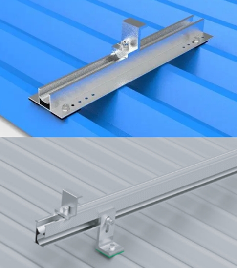
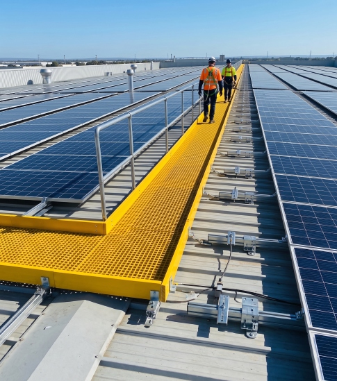
    The mounting structure represents the second-largest driver of embodied carbon in a solar PV system. Selecting between short, segmented profiles and continuous long rails is not a mere installation footnote; it is a fundamental engineering and commercial decision.   Every solar deployment begins with this critical structural choice. Before specifying inverters or configuring cable runs, the mechanical interface with the roof must be established. The market is defined by two primary solutions: continuous horizontal rails and localized mini rails. They are not interchangeable, and the distinction dictates structural load paths, supply chain efficiency, and project margins. The Mechanics of Mini Rails Mini rails are compact aluminum extrusions, typically spanning 250 mm to 600 mm. Rather than deploying full-length continuous tracks across a roofspan, installers position two targeted profiles beneath each module—securing the top and bottom edges prior to final clamping.   Optimal Application Engineered specifically for trapezoidal and corrugated metal roof sheets, these components anchor directly into the roof crest. They utilize self-drilling fasteners integrated with EPDM rubber backing, which instantly compresses to form a robust, weatherproof seal. This localized approach eliminates the need to locate underlying purlins or navigate complex roof flashing.   Advantages: Material Efficiency: Achieves a 30–50% reduction in aluminum mass compared to continuous baseline systems. Commercial Viability: Delivers 25–40% lower overall project costs when factoring in material CAPEX, labor, and logistics. Logistical Optimization: Compact palletization maximizes shipping container density, allowing a standard commercial van to transport volumes that would otherwise require a flatbed truck. Agility: Lightweight design facilitates rapid deployment, often requiring only a single installer for smaller capacities.   Limitations: Load Distribution: Concentrates structural forces into point loads rather than dispersing them across a continuous beam. Environmental Variables: High-wind environments necessitate a higher density of localized fixings per module, which can incrementally offset initial material savings. Roof Compatibility: Strictly incompatible with non-structural roof skins such as tile, slate, or flat membrane surfaces.   The Mechanics of Continuous Long Rails Continuous long rails represent the traditional PV mounting architecture: full-length horizontal aluminum tracks aligned parallel to the roofline. Acting as primary structural beams, these extrusions distribute module weight and aerodynamic forces along their entire span, systematically transferring the load down into the building’s core structure through periodic anchor points. Optimal Application Long rails are the definitive engineering solution for tile, slate, flat membrane, and standing-seam profiles. They are mandatory for high-load environments, including aggressive snow zones, exposed coastal sites, and hurricane-rated geographies. Whether utilizing roof hooks that reach the structural rafters on a slate roof or non-penetrating clamps on a standing seam, the mechanical load path always terminates at the building's structural timber or steel, bypassing the outer roof covering entirely.   Advantages: Structural Integrity: The beam action effectively neutralizes localized point loads, smoothing out dynamic forces. Load Dispersal: Ensures uniform weight distribution across multiple structural members, a critical requirement when calculating against severe snow loads or wind uplift frameworks. Installation Tolerance: Highly forgiving of minor roof irregularities, permitting modules to slide laterally along the extrusion for precise coplanar alignment prior to final torqueing.   Limitations: Logistical Footprint: The bulky extrusions demand longer transit vehicles, increased shipping cycles, and higher freight overheads. Cost & Carbon: Drives up the baseline material CAPEX and embodied carbon per installed kWp. Deployment Velocity: Slower to install, typically mandating multi-person crews for maneuverability.   Comparative Specification Matrix Specification Mini Rails (Segmented Profiles) Continuous Long Rails Optimal Roof Architecture Trapezoidal & corrugated metal Tile, slate, flat, standing seam Mechanical Fastening Self-drilling screws with EPDM sealing into roof crests Roof hooks or structural brackets anchored to rafters Aluminum Footprint (per kWp) 30–50% reduction Industry baseline Overall Project CAPEX 25–40% reduction Industry baseline Extreme Wind & Snow Loads Requires augmented fastener density Native structural suitability Deployment Crew Frequently single-operator Multi-person requirement The Carbon and Logistical Nexus Beyond the photovoltaic modules themselves, the aluminum mounting structure is the second-largest driver of embodied carbon within a rooftop array. While this metric may not appear on standard commercial quotations, it is a glaring variable in any formal lifecycle assessment (LCA).   The root cause is the raw material. Primary aluminum smelting is one of the most energy-intensive industrial operations globally, consuming roughly 14 to 16 megawatt-hours of electricity per tonne. Even when powered by hydroelectricity, the carbon intensity of finished extrusions remains high; if coal-powered, the environmental toll is severe.   This makes mini rails the definitive eco-efficient solution for standard metal roofs. Achieving a 30–50% reduction in aluminum mass translates directly to a proportional drop in upfront embodied carbon. Furthermore, the compact pallet footprint drastically optimizes shipping container density, directly mitigating the Scope 3 transport emissions—and volatile freight overheads—associated with moving the hardware from the manufacturing facility to the installation site.   However, continuous long rails are structurally essential for incompatible roof skins or extreme load environments; substituting them in these scenarios compromises safety. The core issue is not the existence of long rails, but the industry habit of defaulting to them on standard trapezoidal metal structures where mini rails could achieve the same mechanical threshold with half the material. Every kilogram of aluminum optimized out of a system design is a kilogram saved from the smelter.   Strategic Deployment Criteria There is no universal solution, nor should there be. Mini rails and continuous rails are complementary architectures, with their deployment dictated by structural engineering frameworks, geography, and environmental targets: Metal roof, moderate load climate: Mini rails, almost exclusively. Tile, slate, membrane, or standing seam: Continuous long rails, without exception. Exposed, high-wind, or heavy-snow sites: Continuous long rails, regardless of the underlying roof skin. Marginal or mixed conditions: Dictated by strict structural calculation, not catalog default.   A competent engineering and installation team makes this selection deliberately on every project rather than relying on standard inventory habits. For environmentally and financially conscious procurement, the baseline question is: "Can this array be securely mounted using mini rails?" When the technical answer is yes, the low-carbon option aligns perfectly with the most cost-effective solution.   Executive Summary The structural framework is the second-largest source of embodied carbon in rooftop solar. Mini rails minimize the aluminum footprint and localize loads across multiple point fixings, while continuous long rails act as spanning beams to disperse heavy loads and accommodate irregular roof battens. The definitive choice must always be driven by the roof's mechanical capacity and environmental load parameters.   Are you preparing for a solar project? We provide technical consulting and structural support to ensure your assets are built on a solid foundation. Contact us at: fred@sunnect-solar.com    
  • Cable Trays in Solar PV Systems: Functions and Importance
    Cable Trays in Solar PV Systems: Functions and Importance
    Aug, 24 2026
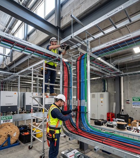
    While solar modules and inverters often steal the spotlight, cable management systems are the unsung heroes of photovoltaic (PV) projects. Cable trays protect, guide, and support PV cables, directly impacting electrical safety, system reliability, and long-term maintenance efficiency. Without them, even top-tier solar arrays risk severe electrical faults.   Here is a streamlined, professional rewrite of your article for maximum impact and readability.   Core Types of Cable Trays Selecting the appropriate tray structure depends on your project’s environment, thermal requirements, and routing complexity: Ladder Type: Provides superior heat dissipation; the standard choice for large ground-mounted plants running high-current DC cables. Perforated: Balances robust support with partial protection against falling objects; ideal for commercial rooftop flexibility. Wire Mesh: Lightweight and highly adaptable for complex cable routes, though it offers less mechanical protection than solid alternatives. Solid Bottom: Delivers maximum protection against debris, moisture, and chemical exposure for specialized industrial applications.   Material Selection Guide Choosing the correct material prevents premature corrosion and costly replacements. Material Key Characteristics Best Applications Hot-Dip Galvanized Steel High strength, economical, durable Large-scale ground-mounted plants Aluminum Alloy Lightweight, natural corrosion resistance Rooftops, coastal installations Stainless Steel (304/316) Superior corrosion and chemical resistance High-humidity, saline, or floating PV Essential Design & Installation Practices To ensure system longevity and safety, strict adherence to installation best practices is non-negotiable: Structural Integrity: Account for wind and snow loads, ensuring support spacing (typically 1.5 to 3 meters) prevents cable sagging and connection stress. Strategic Separation: Physically isolate DC arrays, AC grid cables, and communication lines to eliminate electromagnetic interference. Thermal Flexibility: Incorporate expansion joints on long runs to accommodate thermal expansion, contraction, and uneven ground contours. Grounding & Bonding: Properly ground all tray sections to create an equipotential system, providing a safe path for fault currents and mitigating shock hazards. Note: The most common design pitfalls include ignoring wind loads in open areas, mixing AC/DC cables without proper separation, and neglecting future maintenance access routes. Integrated Solutions by Sunnect Solar Whether integrating with front pillars on ground mounts, navigating delicate roof waterproofing membranes, or adapting to floating PV wave movements, properly engineered cable trays slash maintenance times and elevate safety. Sunnect Solar provides tailored, integrated mounting and cable management solutions—from heavy-duty ground systems to corrosion-resistant rooftop setups. By aligning the support network of your modules with your cabling infrastructure, we help build safer, more efficient, and highly reliable solar power systems.   Are you preparing for a solar project? We provide technical consulting and structural support to ensure your assets are built on a solid foundation. Contact us at: fred@sunnect-solar.com  
  • Types, applications and benefits of Solar Canopies
    Types, applications and benefits of Solar Canopies
    Aug, 17 2026
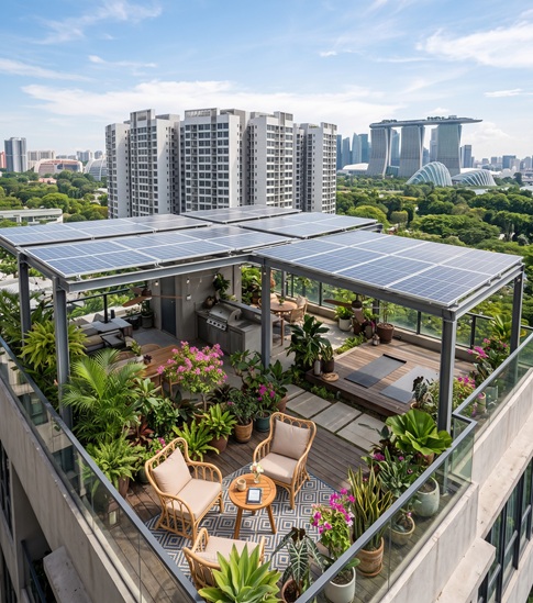
    A solar canopy is an elevated structural system designed to support photovoltaic (PV) modules above parking areas, walkways, patios, and open grounds. By combining overhead weather protection with clean energy generation, solar canopies maximize land-use efficiency without requiring dedicated acreage.   Engineered for a 25 to 30-year lifespan, these systems operate either as grid-tied configurations to leverage net metering or as off-grid setups with battery storage for resilient energy independence. While structural and foundation requirements entail higher upfront capital expenditure than standard rooftop mounting, solar canopies offer compelling long-term returns through vehicle protection, electric vehicle (EV) charging integration, reduced utility overhead, and increased property valuation.   Primary Structural Types Solar Carports: Built over residential driveways, commercial lots, and fleet terminals. They provide shade and weather shielding for vehicles while seamlessly integrating with EV charging infrastructure. Solar Pergolas: Open-framework architectural systems designed for gardens, terraces, and gathering zones, blending ambient light, partial shelter, and on-site power generation. Solar Gazebos: Freestanding, solid-roof structures optimized for parks, recreational facilities, and backyards, combining outdoor aesthetic appeal with reliable decentralized power. Solar Patio Covers: Attached directly to existing buildings or installed as standalone shade structures over decks and outdoor living spaces to lower ambient heat and power auxiliary loads.   Key Sector Applications Residential Shields driveways, carports, and outdoor assets from UV and severe weather. Expands functional outdoor living space across patios, decks, and gardens. Directly offsets household utility rates while powering outdoor lighting, pool pumps, and exterior amenities. Commercial & Industrial Transforms standard parking lots into power-generating hubs paired with level-2 or DC fast EV chargers for staff and clients. Provides energy-producing covered dining and lounge areas for hospitality venues. Lowers peak demand charges and operational expenses for manufacturing plants, logistics hubs, and warehouses. Public & Institutional Schools and Universities: Lowers operating costs while providing visible, real-world educational tools for sustainability. Healthcare Facilities: Couples solar generation with battery energy storage systems (BESS) to supply critical backup power during grid disruptions. Parks and Municipalities: Delivers off-grid, clean electricity for public lighting, municipal amenities, and community gathering grounds.   Advantages of Solar Canopies Solar canopies deliver practical, multi-functional value across residential, commercial, and public spaces by integrating clean power generation directly into everyday outdoor infrastructure. Dual-Purpose Functionality: Combines reliable overhead shelter from sun and precipitation with on-site renewable electricity generation, advancing clean energy independence. Maximum Land-Use Efficiency: Utilizes elevated mounting to preserve ground-level footprint, generating power over existing parking bays, patios, decks, or walkways without requiring dedicated land. Asset Protection & Reduced Maintenance: Shields vehicles, outdoor equipment, and patio furnishings from severe weather and UV degradation, extending asset lifespans and lowering upkeep costs. Architectural Appeal & Property Value: Upgrades outdoor environments with sleek, modern structural aesthetics while providing long-term utility savings that elevate overall real estate value.   Are you preparing for a solar canopy project? We provide technical consulting and structural support to ensure your assets are built on a solid foundation. Contact us at: fred@sunnect-solar.com    
  • Dual-Post Solar Mounting Systems: The Optimal Solution for High-Wind Installations
    Dual-Post Solar Mounting Systems: The Optimal Solution for High-Wind Installations
    Aug, 10 2026
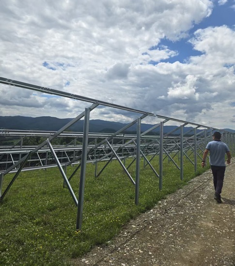
    As the global transition to solar energy accelerates, selecting the optimal mounting infrastructure is more critical than ever. The quality of a mounting system directly dictates the long-term durability, operational efficiency, and overall safety of any solar power plant.   Entering 2026, the Double-Post Solar Mounting System has firmly established itself as one of the most reliable and cost-effective solutions for commercial and industrial (C&I) projects. Purpose-built to conquer extreme weather—including high wind loads and torrential rain—as well as highly uneven terrain, these systems deliver uncompromising structural reinforcement for large-scale solar arrays.   What is a Double-Post Solar Mounting System? A double-post mounting system is a robust, ground-mounted framework that utilizes two vertical support columns to securely anchor photovoltaic panels. This dual-support architecture inherently provides: Optimized Load Distribution: Balances panel weight and environmental stressors evenly across the structure. Enhanced Structural Stability: Provides a rigid, unyielding foundation for the entire array. Superior Wind Resistance: Engineered to remain steadfast in severe weather conditions. Maximized Module Support: Perfectly suited to safely carry modern, large-format solar panels.   Primary Applications: Industrial Solar Projects: Manufacturing plants, large-scale warehouses, and factories. Utility-Scale Solar Farms: Expansive, high-capacity ground-mounted PV parks. Commercial Installations: Shopping complexes, educational institutions, and corporate facilities. Harsh Environment Regions: Geographic areas prone to heavy rainfall, gale-force winds, or challenging topographies.   5 Key Benefits of Double-Post Solar Structures: 1. Exceptional Wind Resistance A standout advantage of the double-post system is its unparalleled ability to endure severe weather. Rigorously engineered to withstand wind speeds of up to 180 km/h, these structures are highly recommended for: Coastal and high-wind regions Open industrial plains Large-scale solar farms Their robust structural integrity prevents panel displacement and guarantees long-term operational reliability. 2. Optimized Load Distribution: The dual-support architecture evenly disperses the physical weight of the solar panels and environmental pressures. This balanced distribution drastically minimizes localized stress, structural fatigue, and long-term material deformation, resulting in a significantly more stable array over time. 3. Ideal for Large-Format Modules: As modern solar projects increasingly adopt larger, high-capacity modules, double-post systems provide the requisite heavy-duty support. They offer tremendous flexibility, seamlessly accommodating multiple panel configurations and both landscape and portrait orientations. 4. Extended Structural Lifespan: Constructed primarily from hot-dip galvanized (HDG) steel and highly corrosion-resistant materials, these structures are built for longevity. Industrial clients benefit from supreme rust resistance, vastly reduced maintenance costs, and unwavering durability in harsh climates—ultimately maximizing long-term ROI. 5. Versatile Foundation Compatibility: Every project site is unique. Double-post systems adapt effortlessly to diverse soil conditions and topographical requirements by supporting multiple foundation types, including driven piles, concrete bases, and screw piles.   Technical Highlights: Engineered to meet stringent industrial standards, premium double-post systems feature: Extreme Weather Rating: Certified wind resistance up to 180 km/h. Layout Flexibility: Full compatibility with both portrait and landscape module arrays. Terrain Adaptability: Optimized for slopes and uneven ground conditions. Premium Hardware: High-grade aluminum clamps paired with stainless-steel fasteners. Robust Framework: Heavy-duty HDG/GI structural steel components. Streamlined Assembly: Intelligent design for rapid, tool-friendly module attachment.   Why Structural Quality is Non-Negotiable: Choosing the right mounting hardware is a vital investment in your solar plant's future. The Risks of Low-Quality Systems: Subpar mounts often lead to severe corrosion, panel misalignment, catastrophic wind damage, and escalating maintenance expenses. The Rewards of Engineered Systems: Investing in high-quality structures ensures uncompromising safety, consistent power generation, lowered operational costs, and an extended system lifespan of 25+ years. The Future of Solar Mounting Systems: As the solar industry evolves, mounting infrastructure is shifting toward: Ultra-high-strength, lightweight materials. Pre-assembled designs for drastically faster installation. Ultra-low maintenance engineering. Advanced, hyper-weather-resistant designs.   Frequently Asked Questions (FAQs): Q1: Which is better—a single-post or double-post solar structure? Double-post systems offer vastly superior stability, higher load-bearing capacities, and drastically improved wind resistance compared to single-post designs. Q2: Are double-post systems safe for high-wind areas? Absolutely. They are purpose-built for extreme weather and are rigorously tested to safely withstand wind speeds of up to 180 km/h. Q3: What materials are standard in premium mounting structures? Top-tier structures generally utilize hot-dip galvanized (HDG) steel for the primary framework, complemented by aluminum clamps and stainless-steel fasteners to prevent corrosion. Q4: Are these systems appropriate for industrial use? Yes. Their inherent strength and durability make them the industry standard for commercial, industrial, and utility-scale installations. Q5: What is the expected lifespan of a solar mounting structure? When engineered properly and heavily galvanized, a high-quality mounting structure will reliably perform for 25 years or more with minimal maintenance required.   Conclusion: A Double-Post Solar Mounting System is far more than a simple metal framework; it is the resilient backbone of a dependable solar installation. Offering unparalleled wind resistance, balanced load distribution, and profound long-term durability, these structures have rightfully become the preferred choice for modern solar projects across India. For industrial and commercial developers who prioritize lasting performance, investing in a robust, engineered double-post system guarantees maximum efficiency and highly optimized long-term returns.   Are you preparing for a utility-scale solar project? We provide technical consulting and structural support to ensure your assets are built on a solid foundation. Contact us at: fred@sunnect-solar.com    
  • The Invisible Backbone: A Deep Dive into Foundation Embedded Anchor Bolts for Solar Mounting
    The Invisible Backbone: A Deep Dive into Foundation Embedded Anchor Bolts for Solar Mounting
    Aug, 04 2026
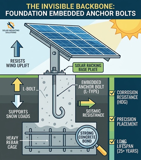
    When you look at a utility-scale solar farm or a robust commercial ground-mount system, your eyes are naturally drawn to the massive arrays of gleaming blue and black photovoltaic (PV) panels. You might notice the precision of the steel or aluminum racking holding them at the perfect angle to capture the sun. But beneath the surface lies the true hero of the entire structural system: the foundation embedded anchor bolt. While they account for only a fraction of a percent of a solar project's total budget, these heavy-duty fasteners carry 100% of the project's structural integrity. If the racking system is the skeleton of a solar array, the embedded anchor bolts are the tendons that bind that skeleton to the earth. In this post, we are going to explore what these critical components are, the immense forces they combat daily, material selection, and the precise sequence required to install them correctly.   What is a Foundation Embedded Anchor Bolt? In solar mounting systems, a foundation embedded anchor bolt (often referred to as a cast-in-place anchor) is a heavy-duty threaded steel rod that is cast directly into a wet concrete foundation—typically a concrete pier, footing, or ballast block. Unlike post-installed anchors (like expansion bolts or epoxy anchors that are added after the concrete has cured), embedded anchors are positioned before the concrete pour. Once the concrete cures around the embedded portion of the bolt, it creates an incredibly strong, permanent connection. The exposed threaded top of the bolt is then used to secure the base plates of the solar mounting structure using heavy-duty nuts and washers. These bolts typically feature a specific design at the embedded end to prevent them from pulling out under extreme tension. The most common shapes include: L-Bolts (or J-Bolts) Or U-Bolts: The bottom of the bolt features a 90-degree (or curved) bend that hooks under the concrete and rebar matrix. Headed Anchor Bolts: A straight threaded rod with a heavy forged hex head or a welded anchor plate at the bottom, providing a massive surface area to resist pull-out forces.   The Forces at Play: Why Anchor Bolts Are Critical Solar arrays act like massive sails. Because they are often installed in wide-open areas to maximize sun exposure, they are subjected to brutal environmental forces. Embedded anchor bolts are engineered to transfer three primary dynamic loads from the racking system directly into the concrete foundation: Wind Uplift (Tension): This is the most dangerous force a solar array faces. High winds hitting the angled face of a solar panel create an aerodynamic lift, much like the wing of an airplane. The anchor bolts must possess immense tensile strength to hold the entire structure down and prevent it from being ripped from its foundation. Snow Loads (Compression & Shear): In northern climates, heavy snow accumulation on panels creates massive downward pressure. While the concrete foundation handles most of the compressive load, the anchor bolts must resist the shear forces generated if the mounting structure attempts to slide or buckle under the uneven weight. Seismic Activity (Lateral & Shear): In earthquake-prone regions, ground acceleration causes violent lateral shaking. Embedded anchor bolts must be ductile enough to absorb these sudden horizontal shear forces without snapping. If an anchor bolt yields or pulls out, the racking system shifts. Even a shift of a few millimeters can induce micro-cracks in the silicon cells of the PV panels, severely degrading energy output. In worst-case scenarios, a bolt failure leads to catastrophic structural collapse during a storm.   Material Selection: The Battle Against Time and Elements Solar installations are designed to last 25 to 35 years. The foundation bolts spend this entire lifespan sitting exactly at ground level or just above it—a zone notorious for moisture accumulation, soil acidity, and fluctuating temperatures. Choosing the right material and coating is non-negotiable. Material / Coating Characteristics Best Use Case Hot-Dip Galvanized (HDG) Carbon Steel High strength carbon steel dipped in molten zinc. The zinc acts as a sacrificial anode, corroding before the steel does. The industry standard for 90% of inland solar projects. Excellent balance of cost, strength, and corrosion resistance. Stainless Steel (304 or 316 Grade) Naturally resistant to oxidation and rust due to chromium content. Type 316 includes molybdenum for added chloride resistance. Coastal environments with high airborne salt, or highly acidic soil conditions. More expensive but necessary for harsh environments. Epoxy-Coated Steel Standard steel bolts coated in a thick, durable epoxy resin to act as a physical barrier against moisture. Highly corrosive chemical environments or regions with stray electrical currents in the soil. Engineering Tip: When using HDG anchor bolts, the nuts and washers must also be HDG. Mixing metals (e.g., placing a stainless steel nut on a galvanized bolt) can trigger galvanic corrosion, rapidly accelerating the degradation of the fastener. The Installation Process: Getting It Right the First Time The primary challenge with cast-in-place anchor bolts is that once the concrete cures, there is zero margin for error. If a bolt is set slightly out of alignment, the base plate of the solar racking will not fit. This requires extreme precision during the foundation phase.   1.Foundation Excavation and Rebar Placement:Preparing the structural matrix. The site is excavated for the concrete piers or footings. A cage of reinforcing steel (rebar) is tied and placed into the excavation. This rebar gives the concrete its tensile strength and provides a framework to anchor the bolts against. 2.Setting the Anchor Bolt Template:Crucial for millimeter precision. Because solar racking base plates are pre-drilled at the factory, installers use a wooden or steel "template" at the top of the foundation form. This template holds the anchor bolts suspended in the exact configuration (spacing and orientation) required by the racking manufacturer. 3.Verifying Embedment Depth and Projection:Checking the engineering specs. Before any concrete is poured, the site engineer verifies two dimensions. First, the embedment depth (how much of the bolt will be buried in concrete) must meet wind-load requirements. Second, the projection (how much thread sticks out above the concrete) must be long enough to accommodate the base plate, leveling nuts, structural washers, and top nuts. 4.Pouring and Consolidating the Concrete: Concrete is poured into the formworks, flowing around the embedded anchor bolts. It is vital to use an industrial concrete vibrator during this step to eliminate air pockets (honeycombing) around the lower portion of the bolt, which would severely weaken its pull-out resistance. 5.Curing and Racking Installation:Do not rush the cure time. The concrete must be allowed to reach its specified compressive strength (usually 28 days for full strength, though racking can sometimes begin sooner based on engineer approval). Once cured, the templates are removed, the racking base plates are seated over the threaded projections, and the structural nuts are torqued to exact specifications.   Quality Assurance and Common Pitfalls Even with the best materials, poor execution can doom a project. Solar EPCs (Engineering, Procurement, and Construction companies) employ strict quality assurance measures for embedded bolts. 1. The Threat of "Plumb" Deviation If bolts are not set perfectly vertical (plumb), installers will struggle to get the racking base plates seated. While minor deviations can sometimes be fixed by slightly enlarging the holes on the aluminum racking base plate, extreme deviations force contractors to cut the bolt off entirely and attempt to retrofit a post-installed epoxy anchor—a costly, time-consuming nightmare that often requires requalifying the engineering stamps. 2. Pull-Out Testing On large utility-scale sites, independent third-party engineers will conduct random "pull-out tests." They attach a specialized hydraulic jack to the exposed threads of an embedded bolt and apply upward pressure that simulates a 100-year storm event. If the bolt slips, the concrete cracks, or the bolt yields before reaching the required load, the entire foundation design must be re-evaluated. 3. Torque Verification Once the solar racking is installed, the nuts on the anchor bolts must be tightened to a specific torque setting. Under-tightening leaves the structure vulnerable to vibration loosening during high winds; over-tightening can stretch the bolt past its yield point, permanently weakening the steel. Installers often use "torque marks" (a line of paint drawn across the bolt thread and nut) so inspectors can visually verify that the nut has not backed off months after installation.   Conclusion The next time you drive past a sprawling solar farm, take a moment to look past the high-tech, sun-tracking photovoltaic panels. Down in the dirt, hidden inside blocks of concrete, thousands of foundation embedded anchor bolts are silently doing the heavy lifting. By demanding precise engineering, uncompromising material quality, and flawless installation sequences, solar developers ensure that these critical fasteners will hold strong—safeguarding multi-million-dollar clean energy assets against whatever Mother Nature throws their way for decades to come.   Are you preparing for a ground solar project? We provide technical consulting and structural support to ensure your assets are built on a solid foundation. Ready to start your next project? Contact us at: fred@sunnect-solar.com      

  • Why Ballasted Solar Mounts Are the Most Secure Option for Flat Roofs?
    Why Ballasted Solar Mounts Are the Most Secure Option for Flat Roofs?
    Jul, 29 2026
    Ballasted solar mounting systems are widely regarded as the safest and most dependable option for commercial flat roofs. Their primary advantage lies in how they separate the structural support of the PV array from the building's waterproof layer. By utilizing gravity and aerodynamic design instead of mechanical fasteners, these systems effectively neutralize the most common vulnerabilities associated with commercial rooftop solar installations. Below is a technical overview of why ballasted designs offer exceptional safety and risk reduction:   1. Protecting the Roof Membrane (Zero Penetrations) Water leakage is the most significant threat to any flat roof, regardless of whether it uses TPO, EPDM, PVC, or modified bitumen. Conventional attached systems necessitate numerous holes to secure the array to the underlying structural beams. Despite premium flashing and sealants, temperature fluctuations and UV exposure will eventually degrade these seals. This inevitably results in leaks, compromised insulation, and invalidated roof warranties. Ballasted configurations completely bypass this issue by sitting directly on the roof's surface, keeping the watertight barrier perfectly intact.   2. Aerodynamic Wind Resistance Rather than fighting wind uplift solely with mechanical pull-out strength, contemporary ballasted mounts are rigorously engineered using computational fluid dynamics (CFD) and physical wind tunnel assessments. By adding wind deflectors—typically on the northern perimeter in the Northern Hemisphere—and shielding the array, the system's aerodynamic behavior is fundamentally changed. High-velocity winds are directed over the modules, transforming potential uplift into a stabilizing downward force. This mechanism allows the array to comply with strict global wind standards (such as ASCE 7 or Eurocode) using significantly less concrete weight than older, non-aerodynamic models.   3. Weight Dispersion and Surface Shielding Concentrated stress, or point loading, is a major hazard for flat roofs. Rigid, mechanically attached systems focus both the dead load (the weight of the equipment) and live loads (environmental forces like wind and snow) onto localized structural supports. In contrast, ballasted designs use broad footings or trays to spread the weight of the concrete blocks, aluminum frames, and solar panels across a much wider footprint. This ensures the weight remains safely within the roof decking's structural limits. Furthermore, protective rubber slip sheets are installed under each tray to prevent physical scraping or chemical reactions between the metal mounts and the roofing material.   4. Managing Thermal Fluctuation Rooftop environments endure drastic temperature swings, causing metal mounting components to expand and contract significantly. When a continuous rail system is bolted firmly to the roof, this thermal shifting can rip the roof membrane, shear fasteners, or warp the PV modules. Since ballasted setups are unattached, the entire system is free to "float" and make micro-adjustments during thermal cycles. This freedom of movement completely prevents thermal shear stresses from transferring into the building's structure.   5. Simplified Maintenance and Decommissioning From an operational standpoint, ballasted mounts make routine roof upkeep significantly simpler. If localized roof repairs are required, the freestanding ballast trays can be temporarily moved aside without the need to cut through waterproof seals or remove structural lag bolts. Furthermore, when the 25-year project lifespan concludes, removing the system leaves the underlying roof completely untouched and unharmed.   Are you preparing for a roof solar project? We provide technical consulting and structural support to ensure your assets are built on a solid foundation. Ready to start your next project? Contact us at: fred@sunnect-solar.com  

  • Unlocking Solar Efficiency: A Guide to Solar Trackers
    Unlocking Solar Efficiency: A Guide to Solar Trackers
    Jul, 21 2026
    Solar panels perform best when facing the sun head-on. This raises a common dilemma: why aren't all solar arrays mounted on motorized systems that follow the sun's path? The short answer is cost and space. For residential use, tracking systems seldom deliver a strong enough return on investment, making a fixed rooftop setup the smartest choice for most homes. Even so, solar trackers have distinct applications where they truly shine.   Defining Sun-Tracking Solar Panels Sun-tracking panels—also referred to as solar trackers or rotating arrays—utilize motorized hardware to produce clean thermal and electric power. Electricity output rises with direct sunlight exposure. In the Northern Hemisphere, south-facing panels naturally capture the most daylight hours. Sun-tracking technology eliminates guesswork by keeping panels at a perpetual right angle to the sun through continuous, automated rotation.   Mechanism: Single-Axis vs. Dual-Axis Trackers Solar trackers complete a daily cycle using one of two primary configurations: Single-Axis Systems: These operate like a seesaw, pivoting along a single axis to track the sun from east to west daily. Dual-Axis Systems: These offer complete freedom of movement, tilting both east-west and north-south to match the sun's precise position across different seasons and times of day. Depending on system software and hardware, trackers can run entirely on autopilot or allow manual user control.   Fixed vs. Tracking Systems: Which Wins? For most residential homeowners, fixed systems provide the most practical and economical solution. A well-exposed roof easily produces enough energy to offset typical utility bills. Because utility providers often cap net-metering capacities, generating excess power beyond historical consumption offers little financial advantage. Fixed rooftop solar remains the industry standard for cost-efficiency. Professional installers design these systems around your roof's unique space, pitch, and orientation. However, for utility-scale solar farms and massive commercial operations, the boost in energy production easily offsets the steeper price tag of trackers.   The Major Benefits of Trackers Because solar efficiency peaks under direct sunlight, a tracker's core advantage is maximum power generation, allowing users to capture every possible kilowatt-hour of daylight. Research from 2022 indicates that tracking systems yield 10% to 60% more energy than fixed arrays. While performance depends on location and tracker type, industry consensus places the average annual boost between 30% and 40%.   Why Solar Trackers Aren't Ideal for Homes Despite their high output, trackers carry significant downsides that limit their viability for residential properties: 1. Steep Upfront Investment Trackers require extra hardware, including motors, gears, and elevated mounting structures to clear space for full rotation. This drives up initial project costs and lengthens the payback period, rarely yielding enough financial gain for an individual homeowner to offset the expense. 2. Demanding Site Conditions To make financial sense, a tracker needs uninterrupted, 360-degree sunlight throughout the entire day. Shading from trees or neighboring buildings creates major hurdles. Furthermore, because local building and electrical codes frequently prohibit elevating rotating systems above slanted roofs, trackers are restricted almost entirely to ground mounts or flat commercial roofs. 3. More Moving Parts, More Maintenance   A major advantage of standard solar energy is its passive, low-maintenance design. Sun-tracking systems, however, introduce mechanical complexity. Because they rely on moving parts, rotating panels generally require more frequent upkeep than stationary setups.   Pros and Cons at a Glance Pros: Significantly higher electricity production. Cons: Higher upfront costs, stricter property requirements, and increased maintenance due to moving parts.   Is Solar Tracking Worth It? Ultimately, while sun-tracking systems deliver higher energy yields, they rarely make sense for residential installations. Because most homes have sufficient roof space to meet their energy needs cost-effectively with fixed panels, tracking systems are best left to large-scale operations. Today, the ideal applications for solar trackers include: Community solar farms Commercial solar projects Utility-scale power generation   Are you preparing for a utility-scale solar project? We provide technical consulting and structural support to ensure your assets are built on a solid foundation. Ready to start your next project? Contact us at: fred@sunnect-solar.com      
  • The Role of Geotechnical Surveys in Solar Farm Success
    The Role of Geotechnical Surveys in Solar Farm Success
    May, 06 2026
    As countries worldwide accelerate their transition toward net-zero milestones, the landscape of the global energy sector is being reshaped by the rapid deployment of utility-scale solar farms. While the industry’s spotlight often falls on high-performance module efficiency, advanced inverter technology, or the complexities of grid capacity and planning consents, the long-term viability and bankability of any ground-mounted PV asset ultimately hinge on one foundational factor: the unseen conditions beneath the surface. A high-quality geotechnical survey acts as the essential bridge between unknown subterranean variables and reliable, evidence-based engineering. By accurately assessing soil behavior, these investigations do more than just fulfill a permitting requirement; they inform the fundamental structural design, actively mitigate construction risks, and provide the financial certainty that developers, EPC contractors, and institutional investors demand. For projects utilizing sophisticated ground-mounted tracking systems or robust fixed-tilt structures, a geotechnical investigation is far from a preliminary formality. It is a strategic imperative that dictates structural integrity, deployment efficiency, cost control, and the multi-decade performance of the asset.   1. Optimizing Foundation Design and Material Efficiency Ground-mounted solar arrays function as massive structural skeletons that rely entirely on driven steel piles or ground screws to safely transfer static and dynamic loads into the earth. The performance of these foundations is not a product of the steel itself, but of the interaction between the metal and the soil—governed by shear strength, skin friction, and bearing capacity. A comprehensive geotechnical survey provides the empirical data required to calculate precise embedment depths, lateral resistance, and axial capacity. Without this verified subsurface data, engineers are forced to operate under conservative, "worst-case scenario" assumptions. Over-engineering by just a few percent across a project consisting of thousands of piles leads to vastly inflated steel volumes and prolonged pile-driving refusal times. This unnecessarily drives up procurement and labor costs. Conversely, underestimating soil reactivity—such as failing to account for expansive clays or liquefaction potential—can trigger settlement, tracking misalignment, or even catastrophic structural failure. Precise geotechnical data eliminates this guesswork, allowing for optimized, lean, and cost-efficient foundation engineering that respects the project's bottom line.   2. Mitigating Construction Risk and Preventing Refusal Delays Subsurface anomalies represent one of the most volatile variables in solar farm construction. Unanticipated rocky strata, high water tables, or subterranean voids can lead to pile refusal, sudden equipment damage, and cascading project delays. Disruptions of this scale not only inflate labor and machinery costs but can also jeopardize strict grid-connection deadlines and the projected revenue timelines tied to power purchase agreements. Early-stage geotechnical probing allows contractors to select the appropriate ramming machinery, plan pre-drilling strategies if necessary, and optimize on-site logistics before a single pile is driven. This proactive, data-driven approach keeps civil works on schedule and prevents the "change order chaos" that often erupts when a contractor encounters unexpected ground conditions halfway through the installation phase.   3. Safeguarding Long-Term Structural Integrity Solar farms are long-term infrastructural assets designed to operate reliably for 25 to 30 years with minimal structural intervention. Even minor differential settlement—where the ground shifts unevenly under the array—can compromise solar panel alignment. This misalignment alters load distributions, puts unnecessary stress on delicate tracking actuators, and ultimately degrades energy yield. A robust geotechnical evaluation assesses settlement potential, slope stability, and groundwater fluctuations. This ensures that the mounting structures are anchored with the precise stability required to withstand extreme wind loads (which can be amplified by tracking systems) and heavy snow loads over their full design life. By ensuring the "feet" of the system are secure, you reduce ongoing operations and maintenance (O&M) overheads significantly.   4. Enhancing Cost Certainty and Investor Assurance In the competitive utility-scale solar market, margins are tightly calculated around the Levelized Cost of Energy (LCOE). Unexpected civil engineering re-designs due to poor soil data can rapidly erode project profitability and spook equity partners. Front-end geotechnical drilling provides developers with complete clarity on material requirements and installation methodologies from day one. This transparency enables accurate EPC pricing, slashes the need for bloated contingency budgeting, and solidifies the assumptions used in financial modeling. Across utility-scale portfolios, the initial capital expenditure (CAPEX) of a thorough soil investigation is negligible—often less than 0.1% of the total project value—compared to the catastrophic financial impact of unforeseen ground failures or redesigns.   5. Combating Subsurface Corrosion and Degradation The longevity of a solar plant relies not only on mechanical stability but also on the chemical stability of its subterranean assets. Geotechnical surveys analyze critical chemical and physical soil properties, including electrical resistivity, pH levels, moisture content, and the presence of aggressive ions like chlorides and sulfates. This data directly informs corrosion mitigation strategies. For instance, it allows engineers to specify the required thickness of hot-dip galvanized sacrificial zinc coatings for steel piles or the specific grades of concrete for ballasted elements. By identifying "corrosive" soils early, developers can implement the correct protection, safeguarding the structural backbone of the array for its entire operational lifecycle and preventing the hidden cost of premature corrosion-related asset failure.   Engineering Clarity from the Ground Up While high-efficiency photovoltaic modules may represent the "face" of solar innovation, the commercial resilience of an installation is rooted firmly in the ground. Without definitive subsurface insight, even the most advanced solar technology remains exposed to avoidable structural and financial risk. An early, thorough ground investigation strengthens every phase of asset delivery—from optimized structural engineering to investor due diligence. It is not merely a compliance checkbox for local authorities; it is a vital risk-mitigation tool that protects margins, timelines, and asset longevity. In the race to net-zero, those who understand their ground the best will be the ones who build the most successful, durable, and profitable solar energy assets.   Are you preparing for a utility-scale solar project? We provide technical consulting and structural support to ensure your assets are built on a solid foundation. Ready to start your next project? Contact us at: fred@sunnect-solar.com      
  • Why Sheep Grazing on Solar Farms is a Win-Win for Agriculture and Energy
    Why Sheep Grazing on Solar Farms is a Win-Win for Agriculture and Energy
    Jul, 01 2026
    Many utility-scale solar projects are now expected to deliver more than clean electricity. Developers, landowners, and local communities increasingly want solar farms to preserve agricultural value, reduce operating costs, and improve long-term environmental performance. This is where agrivoltaics has become one of the fastest-growing trends in the solar industry.   Among different agrivoltaic models, sheep grazing has proven to be one of the easiest and most commercially successful approaches. Instead of leaving land idle beneath solar arrays, sheep naturally control vegetation while continuing agricultural production. The result is a practical solution that benefits both solar developers and farmers without requiring significant changes to existing farming practices.   For EPC contractors and project investors, integrating grazing into solar farms is no longer simply an environmental initiative. It has become a way to reduce maintenance expenses, improve ESG performance, extend equipment reliability, and strengthen relationships with surrounding communities.   Why Are More Solar Farms Choosing Sheep Instead of Mowers? Vegetation management represents one of the largest recurring maintenance costs throughout the lifetime of a solar power plant. Grass grows continuously throughout the growing season, and unmanaged vegetation can shade PV modules, restrict maintenance access, increase fire risks, and attract unwanted wildlife.   Traditional maintenance usually relies on tractors, ride-on mowers, or herbicides. While effective, these methods require repeated labor, fuel consumption, machinery maintenance, and ongoing operating budgets. For large utility-scale projects covering hundreds or even thousands of acres, vegetation management becomes a substantial operational expense year after year.   Sheep provide a biological alternative. Their grazing naturally maintains vegetation at an appropriate height while producing almost no emissions during operation. Unlike heavy mowing equipment, sheep can safely move between support posts, beneath modules, and around electrical infrastructure without causing soil compaction.   The mounting structure also plays an important role in making grazing practical. A properly designed Ground Solar Mounting Structure provides sufficient clearance for sheep movement, allows maintenance vehicles to access equipment when necessary, and minimizes potential damage to cables and structural components.   Vegetation Management Method Labor Requirement Fuel Consumption Carbon Emissions Long-Term Cost Mechanical mowing High High High High Herbicide application Medium Low Medium Medium Sheep grazing Low None Very Low Low   Measured Benefits Beyond Grass Control The advantages of solar grazing extend well beyond reducing mowing frequency. Multiple studies from the U.S. National Renewable Energy Laboratory (NREL), the American Solar Grazing Association, and several European agrivoltaic research programs have shown that integrating livestock into solar farms creates measurable environmental and economic value.   One immediate benefit is lower operating expenditure. Depending on project size and local labor costs, grazing agreements may reduce annual vegetation management expenses by 20% to 40%. Large utility-scale facilities often recover the initial planning effort within only a few operating seasons.   Sheep also contribute to healthier soil conditions. Their movement naturally incorporates organic matter into the ground, while manure returns nutrients that support microbial activity. Better soil quality improves water infiltration, reduces erosion, and encourages native plant diversity beneath the solar array.   Another overlooked advantage involves module operating conditions. Healthy vegetation helps stabilize ground temperatures and reduces excessive dust generation during dry seasons. Cleaner surroundings can reduce soiling on PV modules, supporting more consistent energy production between scheduled cleaning cycles. Operational Area Traditional Practice With Sheep Grazing Vegetation control Repeated mowing Continuous natural grazing Fuel usage Diesel equipment None Soil condition Compaction risk Natural fertilization Biodiversity Limited Improved habitat diversity Community perception Neutral Positive agricultural coexistence   Does Sheep Grazing Affect Solar Power Generation? This is one of the most common questions asked by project developers. Field experience indicates that properly managed grazing does not reduce electricity generation. In many projects, maintaining vegetation at an appropriate height actually helps prevent shading losses around lower module rows.   Successful projects establish clear grazing schedules, fence layouts, water access, and seasonal stocking densities. These management practices allow livestock operations and solar maintenance teams to work independently without interfering with electrical inspections or preventive maintenance.   Project design remains equally important. Appropriate row spacing, module clearance, drainage planning, and structural stability all influence whether livestock integration is practical throughout the system's 25- to 30-year service life.   Planning a Solar Farm That Supports Livestock Although sheep are considered one of the easiest livestock species to integrate with PV systems, successful projects begin during the engineering stage rather than after construction. The layout of the array, the choice of mounting system, cable routing, and maintenance access all influence whether grazing can operate efficiently over the next two or three decades.   One of the first design considerations is ground clearance. Most sheep breeds require sufficient space to move comfortably beneath the modules without becoming trapped around braces or electrical equipment. Clearance also allows maintenance teams to inspect foundations, tighten fasteners, and replace damaged components without relocating the animals.   Cable management deserves equal attention. DC cables should be protected inside cable trays or conduit wherever possible. Loose wiring may attract curious animals and can increase the risk of accidental damage during routine grazing activities.   Fencing and water access should also be incorporated into the initial site plan instead of being treated as later additions. Well-positioned gates simplify rotational grazing, while strategically located water stations reduce unnecessary movement across the site and minimize soil disturbance around inverter stations. Design Factor Recommended Practice Reason Ground clearance Allow comfortable sheep movement Improves grazing efficiency Cable routing Use trays or conduit Protects electrical cables Fence layout Create rotational grazing zones Improves pasture management Water supply Multiple access locations Reduces livestock concentration Maintenance roads Separate from grazing areas Safer equipment access   Can Solar Trackers Be Used for Grazing Projects? Many developers assume grazing is only suitable for fixed-tilt installations, but that is no longer the case. Modern tracker systems are increasingly being designed with livestock compatibility in mind. Proper engineering allows the tracker to rotate freely while maintaining safe distances from animals throughout the day.   A well-designed Horizontal Single Axis Tracker can increase annual energy yield by approximately 15% to 25% compared with conventional fixed-tilt systems, depending on latitude and local irradiation conditions. For utility-scale projects where maximizing energy production is a priority, combining tracking technology with sheep grazing allows operators to improve both electricity generation and land utilization.   The key is selecting tracker systems with sufficient structural rigidity, protected drive components, and carefully planned row spacing. These features reduce maintenance interruptions while giving livestock adequate room to move safely beneath the arrays.   Developers should also coordinate grazing schedules with routine tracker inspections. During annual servicing or actuator replacement, temporary livestock relocation may improve safety for both maintenance personnel and the animals. System Type Typical Energy Yield Land Use Efficiency Suitable for Sheep Fixed Tilt Baseline High Excellent Single Axis Tracker +15% to +25% Very High Excellent with proper design Dual Axis Tracker Higher output Medium Less common   Operating Cost Comparison Over the Project Lifetime Vegetation management may appear to be a relatively small operating expense during the first year of a project. However, when evaluated across a typical 30-year service life, recurring mowing costs can become significant. Fuel prices, labor shortages, equipment maintenance, and contractor fees continue to increase in many regions, making alternative maintenance strategies increasingly attractive.   Sheep grazing changes this cost structure. Rather than paying repeatedly for mowing services, many solar farm owners establish long-term agreements with local farmers. Both parties benefit: developers reduce maintenance expenditure while farmers gain access to additional grazing land without purchasing new property. Cost Category Mechanical Mowing Sheep Grazing Fuel High None Equipment maintenance High Minimal Labor frequency Frequent Periodic supervision Carbon emissions High Very Low Long-term operating cost Higher Lower Illustrative Annual Vegetation Management Cost   Mechanical   Sheep Grazing The chart illustrates the typical reduction in recurring vegetation management costs after adopting managed sheep grazing. Actual savings depend on labor rates, climate, project size, and grazing agreements.   Best Practices for Long-Term Solar Grazing Success A successful solar grazing project depends on more than simply introducing sheep after construction. Long-term performance requires coordination between the solar asset owner, the EPC contractor, the grazing operator, and routine maintenance teams. Establishing clear responsibilities from the beginning helps avoid operational conflicts and protects both the photovoltaic equipment and livestock.   Rotational grazing is widely considered the most effective management strategy. Instead of allowing sheep to roam the entire site continuously, the solar farm is divided into several grazing zones. Animals are moved between these areas according to grass growth, seasonal weather, and vegetation height. This approach prevents overgrazing while maintaining consistent vegetation control throughout the project.   Regular inspections should also include checking fence integrity, water availability, cable protection, inverter enclosures, and drainage channels. Preventive maintenance is significantly less expensive than repairing damage after equipment failures or extreme weather events. Routine Inspection Recommended Frequency Main Objective Vegetation height Every 2–4 weeks Avoid panel shading Fence inspection Monthly Prevent livestock escape Cable protection Monthly Reduce electrical risks Water supply Weekly Maintain animal welfare Structural inspection Quarterly Ensure long-term reliability   Selecting the Right Mounting System for Different Projects Ground-mounted solar farms are the most common choice for agrivoltaic applications, but mounting solutions should always match the project's terrain, climate, and construction requirements. Sites with uneven ground, soft soil, or strict environmental regulations may require different foundation options to balance installation efficiency and long-term structural stability.   For utility-scale grazing projects, fixed ground systems remain the preferred option because they provide wide maintenance corridors and consistent clearance beneath the modules. However, commercial and industrial buildings can also improve land utilization by combining rooftop photovoltaic systems with nearby agricultural operations.   Where roof penetration is restricted, a Ballasted Flat Roof Mounting solution offers an effective alternative. Instead of drilling into the roof structure, ballast provides the necessary stability while helping protect the waterproof layer. This design is commonly used on warehouses, logistics centers, agricultural processing facilities, and industrial buildings where preserving roof integrity is a priority. Project Type Recommended Mounting Solution Typical Application Utility-scale solar farm Ground-mounted system Agrivoltaics and livestock grazing Commercial warehouse Ballasted flat roof system No roof penetration required Agricultural facility Ground or rooftop system Mixed energy production Industrial complex Fixed tilt or tracker Maximum electricity generation   Frequently Asked Questions   Will sheep damage solar panels? In normal operating conditions, sheep rarely damage PV modules or mounting structures. Unlike cattle or horses, sheep are lightweight and do not climb onto the support structure. Proper cable management and secure fencing further reduce operational risks. Which sheep breeds are commonly used? Many projects use breeds such as Dorset, Suffolk, Katahdin, and Texel because they adapt well to grazing beneath solar arrays. Breed selection should always consider regional climate, vegetation type, and local farming practices. Does grazing reduce maintenance work? Yes, but it does not eliminate maintenance completely. Vegetation management becomes significantly easier, while routine electrical inspections, structural checks, module cleaning, and inverter servicing remain part of normal solar plant operation. Can agrivoltaics improve project sustainability? Yes. By producing renewable electricity while maintaining agricultural activity, agrivoltaic systems improve land-use efficiency and support environmental objectives. Many developers also report stronger community acceptance because farmland continues to serve an agricultural purpose instead of being removed entirely from production.   Are you preparing for a utility-scale solar project? We provide technical consulting and structural support to ensure your assets are built on a solid foundation.   Ready to start your next project? Contact us at: fred@sunnect-solar.com      
  • From Parking Lots to Power Plants: Unlocking the Value of Solar Carports
    From Parking Lots to Power Plants: Unlocking the Value of Solar Carports
    Jul, 01 2026
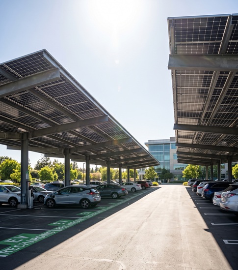
    For decades, the commercial car park has been viewed as a functional necessity—a vast, grey expanse of asphalt dedicated solely to vehicle storage. While these footprints occupy some of the most valuable real estate in a company’s portfolio, they have traditionally sat idle, generating no intrinsic value while contributing to the "urban heat island" effect. Today, that narrative is shifting. Organizations worldwide are now transforming these underutilized spaces into high-performance, revenue-generating clean energy assets through the integration of advanced Solar Photovoltaic (PV) Canopies. By turning a parking lot into a solar power plant, you are doing more than just installing equipment; you are evolving your infrastructure to meet the demands of a decarbonizing economy.   1. Power on Demand: Energy Independence at the Source The most immediate benefit of a solar carport is the ability to generate clean, renewable electricity exactly where it is consumed. Unlike remote solar farms or large-scale rooftop installations that may be constrained by roof integrity, shading, or structural weight limits, solar carports offer unmatched flexibility. By generating power on-site, organizations can significantly offset their energy bills, reducing reliance on the volatile, traditional electricity grid. This is particularly crucial as energy prices continue to fluctuate. With a solar carport, your parking lot becomes a decentralized energy hub. The electricity generated during peak daylight hours can power your facility’s operations, offset cooling loads during hot months, and, when paired with energy storage, provide power long after the sun goes down. This transition from being a passive energy consumer to an active energy producer is a hallmark of modern, resilient business operations.   2. A Masterclass in Efficiency: Zero-Land Decarbonization One of the greatest challenges in the push for Net-Zero is land acquisition. Building massive solar arrays often requires diverting land from other uses, which can be both expensive and environmentally contentious. Solar carports solve this by utilizing space that is already "disturbed" and dedicated to human activity. They require no extra land acquisition, allowing you to hit your ESG (Environmental, Social, and Governance) targets by maximizing the space you already own. This "infrastructure multitasking"—where the same square footage provides both parking and energy generation—is the gold standard for efficient commercial development. It allows companies to scale their renewable energy footprint without sacrificing any existing functionality.   3. Future-Proofing with EV Integration The shift toward electric vehicles (EVs) is no longer a trend; it is a global transformation. As EV adoption increases, your customers, employees, and fleet managers will expect reliable, high-speed charging infrastructure. Integrating EV chargers into your solar carport structure is a "strategic win" that multiplies your investment. By charging EVs directly with solar-generated electricity, you lower the operational costs of your charging network while signaling to your stakeholders that your brand is innovative and future-ready. Furthermore, the combination of solar and EV charging can be bundled into a single construction project, streamlining permitting, trenching, and utility interconnection. This approach saves significant time and capital compared to retrofitting chargers later, value-engineering the process to deliver immediate ROI.   4. An Upgraded Customer Experience: Protection and Comfort A solar carport is more than just a mounting system; it is a premium amenity. In many climates, the "parking experience" is a major pain point for employees and customers alike. Vehicles left in open lots are exposed to blistering UV rays in the summer, torrential rain, and snow in the winter. A solar canopy provides immediate, tangible relief. By keeping vehicles shaded and cool, you significantly reduce the need for air conditioning upon startup, which saves fuel and improves local air quality. For employees, this protection improves daily satisfaction and workplace comfort. For retail customers, shaded parking can even act as a competitive differentiator, encouraging longer visit times during hot weather. It transforms a mundane parking lot into a sheltered, comfortable environment, directly enhancing your facility’s appeal and boosting brand sentiment.   5. Engineered for Durability and Performance Modern solar carport structures are built for the rigors of high-traffic environments. We move far beyond the "steel monsters" of the past; today’s designs are modular, aesthetically pleasing, and highly durable. Available in versatile single-row, double-row, and long-span configurations, these structures are engineered to optimize solar exposure, maximize traffic flow, and ensure ease of vehicle clearance for everything from compact sedans to heavy-duty delivery fleets. These systems are built to withstand extreme weather, from hurricane-force winds to heavy snowfall, utilizing high-grade materials like hot-dip galvanized steel and anodized aluminum. This durability ensures a 25+ year lifespan, providing a stable foundation for your company’s long-term decarbonization goals.   6. The Financial and Strategic Advantage Beyond the immediate utility, solar carports provide a compelling financial case. In many jurisdictions, businesses can leverage significant tax incentives, such as investment tax credits, and utilize accelerated depreciation to recover capital costs faster. Furthermore, as net-zero mandates become the regulatory norm across many regions, solar carports help improve your building’s EPC rating and overall market valuation. Properties equipped with renewable infrastructure consistently attract higher occupancy rates and command better lease values. They signal to investors and tenants that your property is a forward-thinking, resilient asset, rather than a depreciating liability.   Why Partner with Us? Whether you operate a retail park, a corporate headquarters, a logistics hub, or a municipal estate, the parking lot is no longer just a place to leave a vehicle. It is your next great clean energy asset. At Sunnect Solar, we specialize in delivering turnkey, engineered solutions that combine high-efficiency solar generation with seamless charging integration. We don't just build structures; we build value, resilience, and sustainability into the heart of your property. Stop viewing your car park as just asphalt. Start viewing it as the powerhouse of your future operations.   Ready to start your next project? Let’s discuss how we can turn your parking space into a revenue-generating, sustainable asset. Contact us at: fred@sunnect-solar.com      
  • How to prevent rust at weld points on galvanized solar mounting structures
    How to prevent rust at weld points on galvanized solar mounting structures
    May, 06 2026
    This is a comprehensive guide to Corrosion Protection for Welded Galvanized Steel Structures. When galvanized steel is welded, the intense heat consumes the protective zinc layer, leaving the steel exposed to the atmosphere. If left untreated, these weld joints become the "weakest link," leading to premature structural failure.   Technical Guide: Corrosion Protection for Welded Galvanized Steel Joints In industrial and solar mounting applications, galvanized square steel is a standard material choice. However, the welding process is inherently destructive to the protective zinc coating. To maintain a 25-year structural lifespan, you must implement a systematic post-weld restoration process.   1. Pre-Weld Preparation: The Foundation Effective corrosion prevention begins before the torch is lit. Localized Dezincification: Before welding, grind away the galvanized layer approximately 20–30 mm on both sides of the joint using an angle grinder or abrasive paper. The Logic: Health: Prevents the inhalation of toxic zinc fumes during welding. Weld Quality: Molten zinc can mix into the weld pool, causing porosity, brittleness, and cracking. Removing it ensures a clean, high-strength structural bond.   2. The Five-Step Post-Weld Restoration Strategy Restoring the protection is a precise, multi-layered chemical and mechanical process. Step 1: Cleaning and Decontamination Welding slag, spatter, and oxidation are highly corrosive and must be fully removed. Mechanical Removal: Use a wire brush or angle grinder to expose bright, clean metal. Solvent Degreasing: Wipe the area with alcohol or a professional metal cleaner. Residual oil or hand sweat can cause the paint to delaminate, rendering the repair useless. Step 2: Restoring Cathodic Protection (The Zinc Layer) This is the most critical step. You must restore the "sacrificial" protection that makes galvanized steel so effective. Cold Galvanizing Compound: Apply a high-quality cold-galvanizing paint with a zinc content of $\ge$ 92% in the dry film. Application: Apply 2–3 layers, allowing 30 minutes of flash-off time between coats. Unlike decorative silver paints, true cold galvanizing provides active cathodic protection, meaning the zinc will corrode instead of the steel. Step 3: Enhancing the Barrier (Epoxy Zinc-Rich Primer) Once the zinc layer has cured, apply an epoxy zinc-rich primer ($\ge$ 80% zinc content). This layer serves as a high-density chemical barrier that seals the weld and prevents moisture from reaching the base metal. Step 4: Weatherproof Topcoating The zinc-rich primer protects against rust, but it is often vulnerable to UV and mechanical wear. Acrylic Polyurethane Topcoat: Apply 1–2 coats of a UV-resistant topcoat. This provides a durable, chemical-resistant shield that protects the primer from environmental degradation. Aesthetics: Choose a finish—typically silver-gray—to ensure the repaired joint blends seamlessly with the rest of the structure. Step 5: Auxiliary Sealing (For Severe Environments) For structures in coastal, high-salinity, or underground environments, standard painting may be insufficient. Heat-Shrinkable Sleeves: For pipe joints, use a heat-shrinkable sleeve with hot-melt adhesive. This creates an airtight, physical seal that is impervious to moisture. Anti-Rust Wax: For intricate crevices or joints that cannot be easily painted, inject anti-rust wax. This displaces moisture and stays flexible, providing long-term protection in hard-to-reach areas.   3. Quality Assurance and Maintenance To guarantee a 25-year service life, you must manage the assets proactively. Environmental Adaptation: In "salt-fog" or high-humidity environments, increase the total Dry Film Thickness (DFT) and consider upgrading to high-performance fluorocarbon topcoats for superior chemical resistance. Routine Inspection: Treat weld joints as critical infrastructure. Inspect coatings every 1–2 years. If mechanical damage (scratches or chips) occurs, perform a "spot touch-up" immediately to prevent rust-creep under the remaining paint. Safety Standards: Always ensure workers wear proper respirators rated for metal fumes and use adequate ventilation, especially in confined spaces.   Conclusion Post-weld rust prevention is not merely "touch-up painting"; it is the reconstruction of an electrochemical protection system. By strictly controlling surface preparation, applying high-zinc compounds, and sealing the joint with a weatherproof barrier, you ensure your project remains structurally sound and visually pristine for decades.   Are you planning a project that requires long-term structural durability? We provide expert guidance on material selection and corrosion mitigation for solar, commercial, and industrial steel structures. Contact us at: fred@sunnect-solar.com    
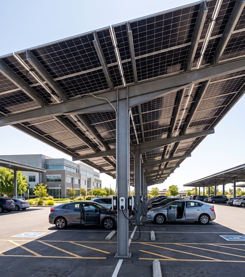
leave a message

leave a message
If you are interested in our products and want to know more details,please leave a message here,we will reply you as soon as we can.

Home

Products

whatsApp

Contact

leave a message
If you are interested in our products and want to know more details,please leave a message here,we will reply you as soon as we can.